 Loading... Please wait...
- Home
- Solaris Blog
- IronRidge Racking: The Complete Guide
Products
- DC Appliances
- Solar Refrigerators and Freezers
- Solar Panel Kits
- Solar Panels
- Solar Generators
- Inverters
- Inverter Monitoring
- Inverter Accessories
- Balance of Systems
- Racking and Mounting
- Rails
- Flashings
- Splice Kits
- Stopper Sleeves
- Conduit Mounts
- Attachments
- Brace Assembly
- Base Mount
- Brackets
- Bolts
- Clamps
- Caps
- L-Feet
- Washers
- Skirt
- Lugs
- Tilt Legs
- Hooks
- Stand-Offs
- Ballast Bay
- Top of Pole Mount
- Side of Pole Mount
- Flush Mount Kits
- Ground Mount Kits
- Roof Mount Kits
- Hardware Packages
- Wire Management
- Batteries
- Battery Accessories
- Charge Controllers
- Tools and Supplies
- View All Products
IronRidge Racking: The Complete Guide
Posted by Brandi Casey on 14th Oct 2019

IronRidge is a global leader in solar racking founded in the mid-1990’s and has since supported the growth of the industry by developing code-compliant racking solutions for roof and ground mount solar installations. The company’s racking components are designed and tested to withstand extreme weather conditions and are certified for compliance with the latest engineering and building codes.
In this IronRidge racking complete guide, we will be taking a comprehensive look at the entire IronRidge product series lines, examining numerous roof top and ground mount solutions, and we will take an in-depth look at how to design an IronRidge racking system for many system types and mounting applications.
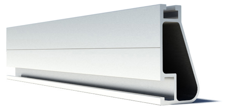
To begin, the XR Series rails are the structural foundation of all IronRidge racking solutions. The signature curve of the rails helps them to resist uplift, product against buckling, as well as safely and effectively transfer loads into the building structure. Their superior spanning capacity decreases the number of necessary roof attachments, which reduces material costs as well as installation time.
The rails are made from 6000-series aluminum alloy and are protected with an anodized finish, which prevents structural corrosion and enhances overall aesthetics. The series is composed of the XR10, XR100 and XR1000 series, each designed to accommodate structural and environmental conditions specific to your geographic area.
IronRidge is compatible with flush, flat and ground mount solar racking applications, and are compatible with nearly every roof type. Their flush mount solutions include the FlashFoot2, L-Feet Attachments, Knockout Tile and the All Tile Hook. While their flat roof mount solutions offer Tilt Leg, Flat Roof Attachments and BX Chassis. In compliance with industry norms, their Ground Mount series uses the XR1000 series rails which are built to handle extreme climates. They also offer an industry leading 25-year product warranty.
See Here: IronRidge Warranty
To gain a better understanding of the various solutions by IronRidge, we have outlined their various product offerings by racking location type: Flush Roof, Flat Roof and Ground Mount. Which attachment product line within the series will depend on your roof type, roof space, structural engineering requirements and aesthetic preference.
We will be going over the various product lines and options available form IronRidge, use the quick links below to jump to the sections you are most interested in.
In this complete guide of IronRidge racking solutions, we will be looking at the following:
I. IronRidge Signature Components
b. UFO Family
c. CAMO
II. Flush Roof Mount Solutions
a. FlashFoot2 - Asphalt Shingle
b. L-Feet Attachments – Metal
c. Knockout Tile – Tile
d. All Tile Hook - Tile
III. Flat Roof Mount Solutions
a. Tilt Legs – Tilt Mount
b. Flat Roof Attachments – TPO, PVC, KEE
c. BX Chassis - Ballast
V. How to Design an IronRidge Racking System
a. Design an IronRidge Flush Mount System
b. Design an IronRidge Tilt Leg System
c. Design an IronRidge Flat Roof Attachment System
d. Design an IronRidge BX Chassis System
e. Design an IronRidge Ground Mount System
See Here: IronRidge Racking for Sale
I. IronRidge Signature Components
To begin our in-depth look into IronRidge racking, we will be looking at the primary series lines that compose IronRidge’s product lines. The first of these being their structural foundation, the XR Series rails, followed by the integrated grounding solutions offered from their UFO series line, and CAMO end clamps.
a. XR Series Rails
As previously noted, the XR Series rails are at the heart of all IronRige racking solutions, from tilted and flat roofs - to ground mount installations. The rails are designed to withstand moderate, heavy and extreme load capacity and are available with clear or black for roof mount arrays, and clear for ground mount arrays.
See Here: IronRidge XR Rail Tech Brief
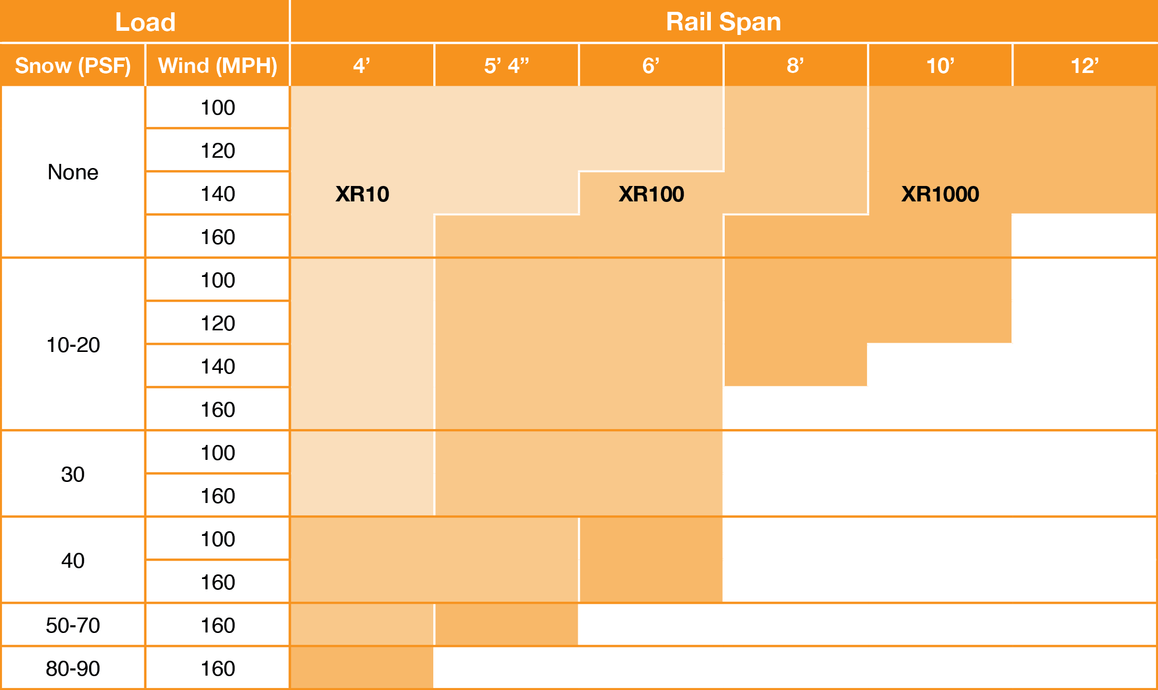
The XR10 Series can handle between 0 to 30 PSF snow load, up to 160 MPH wind speeds, and can be installed between a 4’ and 6’ span.
The XR100 rail is the most popular residential roof top solution from IronRidge and can handle between 0 to 70 PSF snow load, up to 160 MPH wind speeds, and can be installed between a 4’ to 8’ span.
The XR1000 series is predominately used for ground mount arrays but may be used in roof top applications where extreme weather is prevalent. The rails can handle between 0 to 90 PSF snow load, up to 160 MPH wind speeds, and can be installed between a 4’ and 12’ span.
The below chart offers a more detailed overview of these figures.
 IronRidge’s UFO family bonds solar modules directly to the
rails, which eliminates the need for separate grounding hardware and are fully
tested to the UL2703 standard. UFO hardware creates parallel grounding paths
throughout the racking system by forming secure electrical bonds with both the
module and the XR rail. This integrated grounding allows for easier
installation, and a safer install.
See Here: IronRidge Class A Fire Rating
Grounding begins at the bonding attachment hardware, which attach the L-foot to the rail. The UFO universal fastening object (mid-clamp), secures the solar modules to the XR rails (grounding the modules), and is compatible with a wide range of module depths. While stopper sleeves snap onto the UFO to form a bonded end clamp. Bonded splice bars use self-drilling screws to form a secure, grounded connection without the need for bonding traps. Finally, a single grounding lug connects an entire row of PV modules to the grounding conductor.
See Here: UFO Family Tech Brief
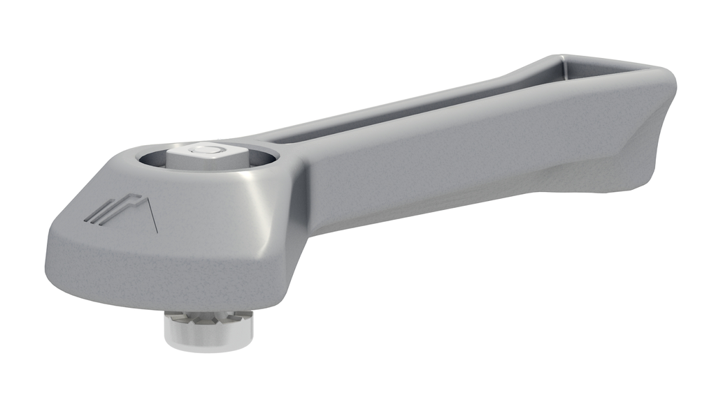 For a finished look, IronRidge offers the CAMO hidden end
clamps
, which are an invisible fastener that secures solar modules flush to
rail ends, creating a clean appearance. The CAMO works with nearly all solar
panels and install without the need for tools or torque specifications.
The easy to install CAMO end clamp is compatible with a number of module dimensions and can be included in both roof top and ground mount systems.
See Here: CAMO Tech Brief
See Here: CAMO Installation Manual
Accessories include system completion components such as wire clips, and end clamps. Wire clips allow for easy and safe wiring maintenance while the end clamps create a polished look for the system and keep dirt and debris from building up within the rails.
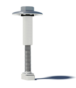
For microinverter and inverter with optimizer systems, IronRidge also makes the microinverter attachment bolts, which allow you to install the microinverter with a single bolt on either the solar panel frame, or the rail itself.
II. Flush Roof Mount Solutions
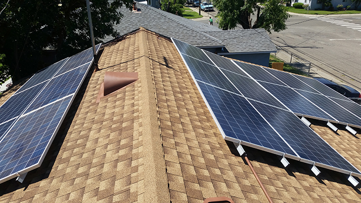
IronRige’s flush mount roof solutions are compatible with Asphalt Shingle, Metal (with the addition of metal roof attachments), Flat Tile, S-Tile, and W-Tile roofs.
| Roof Type | Compatible Mounts |
| Shingle | FlashFoot2, L-Foot Attachments, Tilt Leg |
| Metal | L-Foot Attachments, Tilt Leg |
| Tile | L-Foot Attachments, Tilt Leg, All Tile Hook, Knockout Tile |
IronRidge offers unique structural features, such as curved rails and reinforced flashings. These design innovations are part of the reason why their products are fully certified, code compliant and backed by their 25-year warranty period.
All racking components are strength tested and are PE certified, IronRidge offers PE-stamped engineering letters available in most states on their website. The equipment is Class A Fire rated, which means they are certified to maintain the fire resistance rating of the existing roof. All complete racking solutions and components are also UL25703 listed.
See Here: IronRidge Flush Mount Data Sheet
See Here: IronRidge Flush Mount Installation Manual
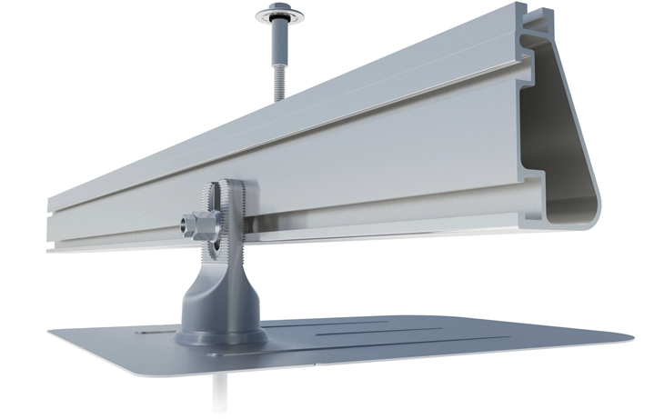
For asphalt shingle flush mount installations, IronRidge’s conduit mounts provides versatile support for a number of electrical accessories, allowing for a clean install and proper wire maintenance. The conduit clamp slides into place without the need for tools and can be positioned in any direction. The cap twists on, creating a seal against water and providing elevated mounting. The deck screw secures to the roof deck and does not need to be installed on a rafter. The attachment flashing utilizes the same FlashFoot2 (FF2) design to create redundant layers of protection against water.
See Here: Conduit Mount Tech Brief
Conduit Installation Manual
a. FlashFoot2 – Asphalt Shingle
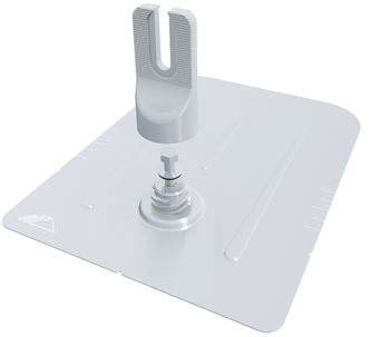 IronRidge’s FlashFoot2 series boasts a unique three-tier
water seal design, which is elevated and encapsulated, delivering multiple
layers of protection against water intrusion. The flashing is completed with a
twist-on cap, which encapsulates the lag bolt and locks into place with a
simple twist. The cap delivers superior structural strength by aligning the
rail and lag bolt into a concentric load path.
This varies from traditional solar attachments, which have a horizontal offset between the rail and lag bolt. This offset introduces leverage on the lag bolt and decreases uplift capacity. The FlashFoot2 is the only flashing that aligns the rail and the lag bolt, which results in a stronger attachment for the system.
The three-tier water seal utilizes an elevated platform, which diverts water away. A stack of components raises the seal up one inch. The seal is then fully encapsulated by the twist-on cap. This innovative design enabled IronRidge to become the first solar attachment to pass the TAS-100 Wind-Driven Rain Test.
See Here: IronRidge FlashFoot2 Tech Brief
Installation is made easy with built in features on the flashing itself. Alignment makers allow system installers to quickly align the flashing with chalk lines to find pilot holes. Rounded corners make it simpler to handle and insert under the roof shingles. While reinforcement ribs help to stiffen the flashings, which prevent any bending or crinkling during installation.
See Here: IronRidge FlashFoot2 Installation Guide
b. L-Feet Attachments – Metal Roofs
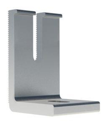 The same L-Foot solution used with the IronRidge FlashFoot2
and other roof mount solutions with the use of their square bolt bonding
hardware. The L-feet can be paired with most metal roof attachments, like those
from S-5! The L-foot attaches to the metal roof clamp by a bolt that comes
included with the metal roof clamps, the L-foot is then connected to the XR
rail via the bonding hardware connector.
S-5! clamps are compatible with a number of metal roof shapes, and pairs them with the corresponding metal roof attachment hardware. You can view the available roof type options here. The number of clamps needed for the system is calculated form your attachment points, i.e., if your system has 45 attachment points, you will need 45 each of the L-feet, attachment hardware and metal roof clamps.
c. Knockout Tile – Flat Tile, S-Tile and W-Tile Options Available
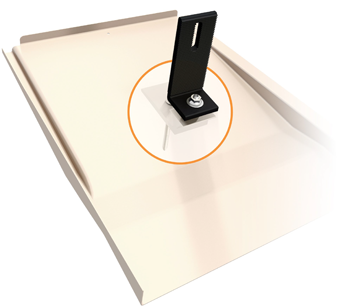 IronRidge offers two innovative solutions for tile roof
installations, which can be both complex and messy through traditional methods.
Oftentimes the installer will need to modify their existing tiles to ensure
that the racking attachment hardware will fit. This can make it difficult to
align mounting components and can lead to broken tiles.
See Here: Knockout Tile Installation Guide
The Knockout line offers a solution, by providing a replacement mount tile flashing that rapidly and reliably integrates the flashing into your existing tile. The form fitting components fully encapsulates the waterproof seal, maintaining similar water-tight conditions like those outlined under the FlashFoot2.
The universal base is strong and light weight, with a compact footprint. The Knockout Tile can be replaced anywhere along the rafter and in any orientation. The universal base can be used with flat, S and W flashings. A single lag is made possible by minimal offset between the lag bolt and the L-foot which improves structural performance around 40% higher loading capacity than a number of competing roof penetrations.
See Here: Knockout Tile Tech Brief
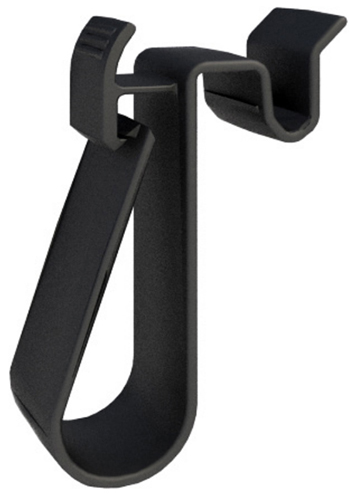
d. All Tile Hook Flashing – Flat Tile, S-Tile and W-Tile Universal Solution
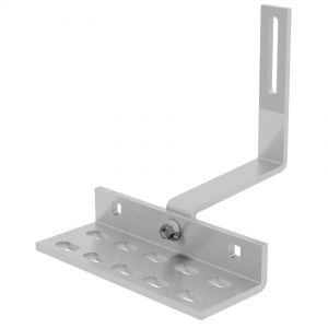 The All Tile Hook is compatible with flat, S and W tile
roofs, and includes 7/16" mounting hardware and optional deck flashing,
which makes single socket installation possible. Watertight conditions are
created by applying sealant to the hook or deck flashing prior to module
placement.
IronRidge’s All Tile Hooks offer a cost effective, easy to install and reliable solution for any tile roof mount installation. The Knockout tile can be added for a completed look to the system as well. Installation is easy with the All Tile Hooks, with no shaving or modification of your existing tiles required.
See Here: All Tile Hook Flashing Manual
See Here: All Tile Hook Installation Manual
III. Flat Roof Mount Solutions
IronRige’s flat mount roof solutions are compatible with Asphalt Shingle, Metal (with the addition of metal roof attachments), Flat Tile, S-Tile, W-Tile, TPO, PVC and KEE roof TOPS. L-feet and attachment hardware are required for tilt leg solutions for metal, and tile roof types.
| Series | Compatible Roof Types |
| Tilt Legs | Asphalt Shingle, Metal, Tile |
| Flat Roof Attachments | TPO, PV, KEE |
| BX Chassis | Ballast Installation |
a. Tilt Legs – Asphalt Shingle, Metal, Flat Tile, S-Tile and W-Tile
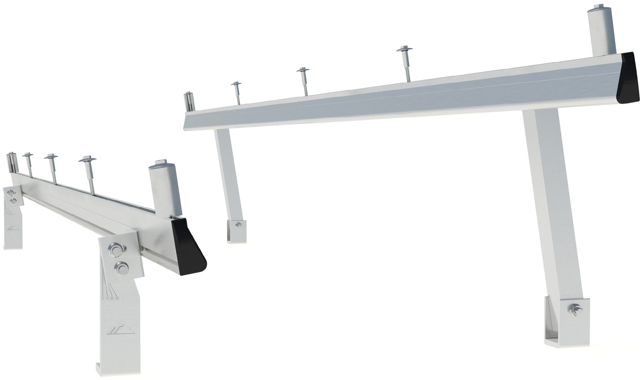 IronRidge Tilt Legs are available up to 30°, all kits
variations include both the south and north tilt leg and necessary hardware.
The legs come in multiple lengths and offer a wide-angle range. By utilizing
the integrated bonding capabilities of UFO hardware, the tilt legs are securely
bonded to and through the rails.
The Tilt Legs are roof-friendly and compatible with a number of roof types, they are compatible with industry standard attachments, and can be retrofitted to fit almost any roof composition.
Tilt Legs offer a cost-effective solution for compatible flat roof applications, and offer more flexibility in design than ballast systems, which require strong load bearing capabilities to pass inspection. With the lightweight IronRidge tilt legs, additional engineering requirements outside of industry standards is not necessary.
See Here: IronRidge Tilt Leg Data Sheet
See Here: IronRidge Tilt Leg Installation Guide
b. Flat Roof Attachments – TPO, PV and KEE
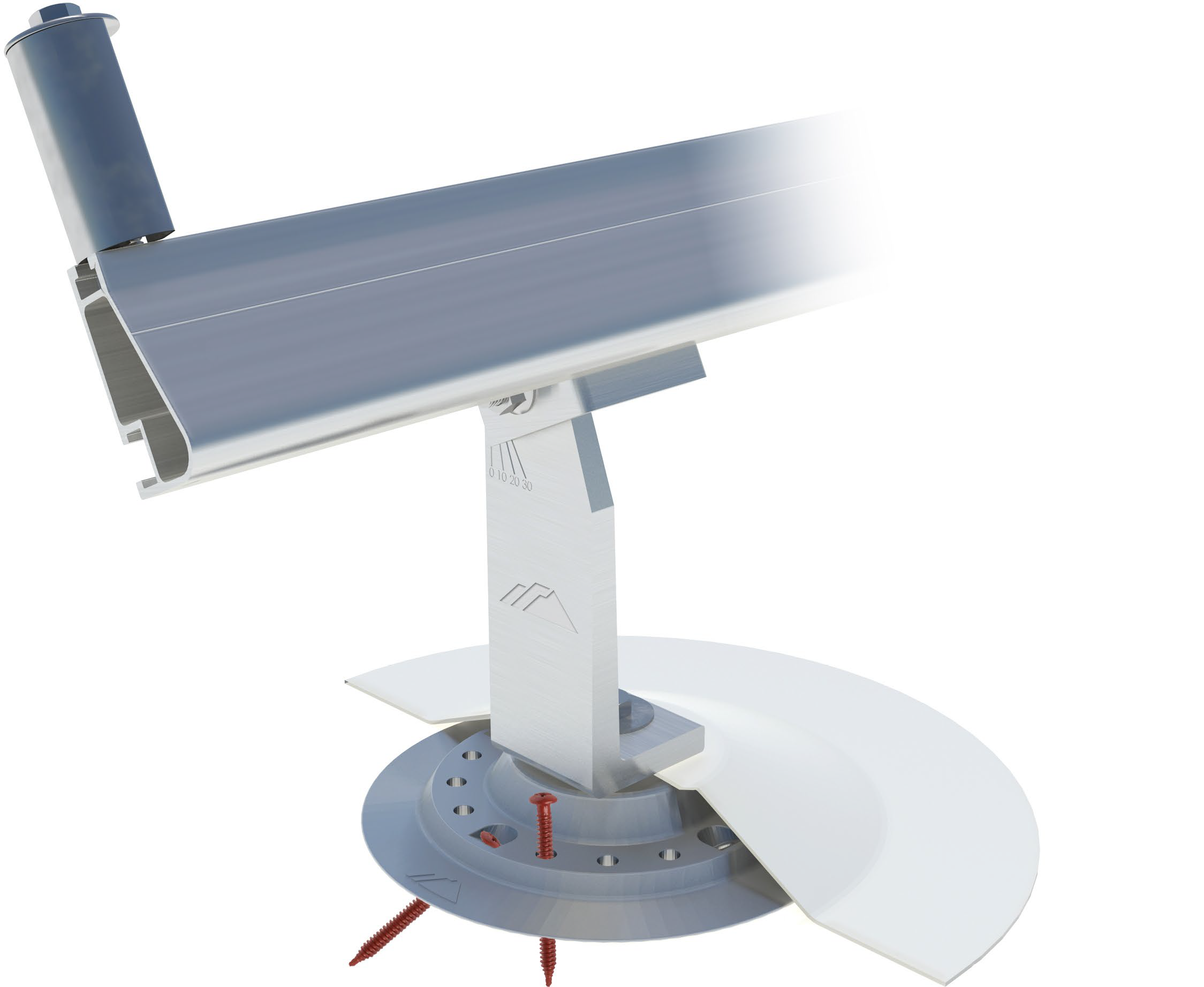 The IronRidge Flat Roof Attachments are specifically made
for roofs with low slopes between 0° and 6°. Flat Roof Attachments are similar
to tilt legs, in that they also avoid the barriers in system approval for not
meeting high load bearing standards. The Flat Roof Attachment utilizes a
high-strength cast aluminum base and 16-point fastening pattern which enables a
wide range of design options for low sloped roofs.
Water sealing is made possible with the use of a pre-installed washer, and “blind hole” that seals the attachment from above. The formed membrane covers are matched and certified to major roofing brands to ensure seamless compatibility.

The 16-point fastening pattern includes 12 straight and 4 angled fastening options. This provides maximum efficiency and versatility with wood, steel, decks, beams and even concrete slabs.
See Here: IronRidge Flat Roof Attachment Tech Brief
See Here: IronRidge Flat Roof Attachment Installation Guide
c. BX Chassis – Ballast Installation
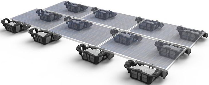
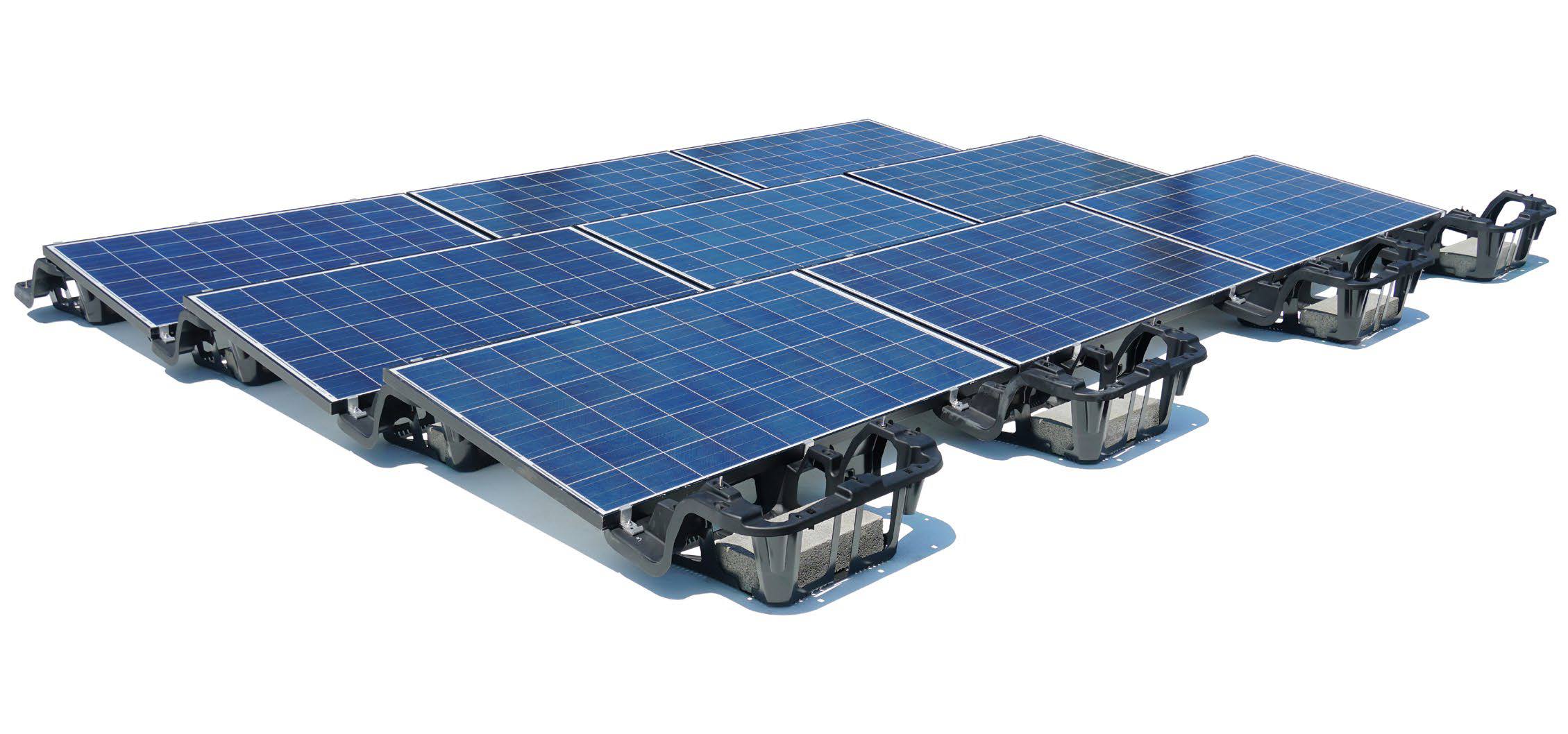 Ballast flat roof mount systems are compatible with a
number of different flat roof faces. The arrays are designed to handle a large
number of panels and are typically used in large scale commercial applications.
This is in large part due to the amount of weight (load) that is required of
roofs. Commercial warehouses, and large offices are ideal locations for ballast
bay racking systems.
The IronRidge BX Series offers superior density and design flexibility through its glass reinforced BSAF Ultramid BX Chassis. Ultramid polyamides boast exceptional mechanical strength, rigidity, thermal stability and impact resistance. The BX Chassis is designed to handle extreme structural loading and is shaped to be roof-friendly and easier to install than traditional ballast bays. Chassis have 5° and 10° options.
See Here: IronRidge BX Chassis Tech Brief
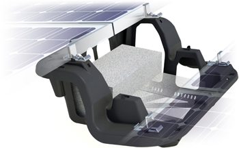 The ballast bay acts as the base for concrete blocks,
saving valuable roof space. The wide base allows for weight distribution and
reduces point pressure. The openings along the bottom and corners prevent water
from pooling, which helps fight against weathering and time in cleaning
maintenance of the system.
The BX series is flexible and can either be fully ballasted, fully anchored, or a hybrid combination optimized for individual site conditions. In combination with an IronRidge Flat Roof Attachment Kit, the BX can eliminate hundreds of pounds of required ballast weight and achieve configurations as light as 3 PSF. Fastening methods can also be optimized for existing roof structures and pre-approved membranes to maintain membrane warranties.
See Here: BX Data Sheet
See Here: BX Installation Guide
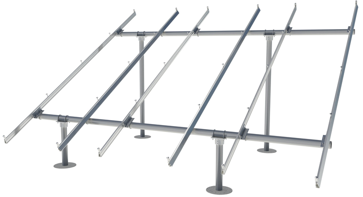
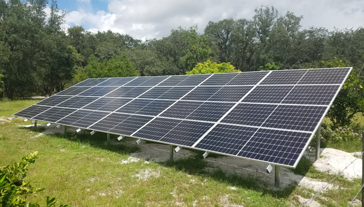
IronRidge Ground Mount racking solutions are one of the most popular ground mount solutions on the market. Their system combines the strength and load capabilities with the XR1000 with schedule 40 (locally sourced) steel pipes or mechanical tubing. The rugged construction of steel and aluminum ensure durability and high wind and snow load capabilities. IronRidge Ground Mount systems include pre-stamped engineering letters that are available in most states.
IronRidge Ground Mounts work in any site and can be installed on all terrains. The mounts offer a cost-effective solution for sites with challenging terrains and steep grades. The mounts work with a variety of foundation options including concrete piers and driven piles.
See Here: IronRidge Foundation Tech Tips
The mounts are easy to install and can be configured between 3 to 5 rows high and up to approximately 25 columns. Diagonal bracing is available for sites that experience high wind speeds and require additional structural support. The systems can be configured between 0° and 45°, though 25° and 30° are recommended for most ground mount installations.
See Here: IronRidge Ground Mount Data Sheet
See Here: IronRidge Ground Mount Installation Guide
V. How to Design an IronRidge Racking System
All of the above systems can be configured utilizing the IronRidge design tool, which is available to installers and DIYers on IronRidge’s website. After creating your account, you will be taken to your Projects page, three you can click on New project, and design a pitched roof, attached flat, ballasted flat, or ground mount system .
After selecting your system type, you will be asked to input the site address. Note, it is important to include the site address, or at least zip code if the site is unknown, this way, the IronRidge tool can accurately account for your:
- Risk Category
- Snow Load
- Wind Speed
- Wind Exposure
Sites with higher than average wind speeds should input maximum data here.
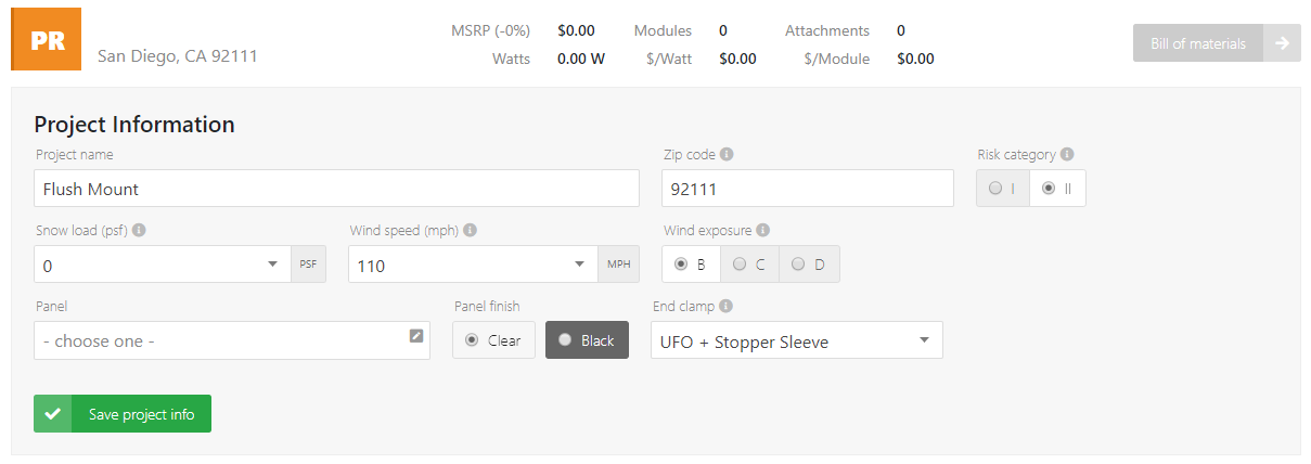
You will then put in the manufacturer and model number of your solar panel. It is important to include the correct module so the bill of materials that is generated is accurate. For example, the depth of the panels (typically 35MM, 40MM or 45MM) will affect which mid and end clamps will be needed for the system.
After this information is completed, the next steps vary depending on which racking solution you are designing for. Below, we have outlined the next steps for flush mount, tilt mount, flat roof attachment, ballast and ground mount systems .
a. Design an IronRidge Flush Mount System
Select New Project and select the “Pitched Roof” design tool. You will be prompted to begin entering your Roof Information. After completing the required data above, select your roofing material – this will affect which roof attachment will be required for your system. After inputting this information, the tool will automatically generate the attachment point you need.
Remember for metal roofs, you will need the IronRidge L-feet, the attachment hardware, and metal roof clamps which need to be sourced from another manufacturer such as S-5! or SnapNrack.
- Comp Shingle – Flashfoot2
- Tile (Flat, S and W) – All Tile Hook or Knockout Tile
- Metal – L-Foot (plus metal roof clamps)
The automatic building height is set to 30ft which is average for most residential buildings. The roof slope is set to 9° or a 2/12 pitch. Typical roof tops are a 4/12 (18°) or 5/12 (22°) pitch. The default rafter spacing of 24 inches is also standard for most roof types.

Next, you will begin adding the roof sections, you can elect to design your system in either portrait or landscape orientation then set your number of rows (panels high) and columns (panels across). The dimensions of the system will be shown so you can accurately design your system.
Note: Most counties require a 3’ layback on either side of the roof (and sometimes the ridge) to comply with fire safety regulations.
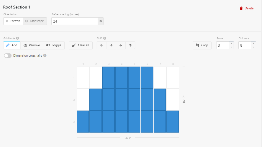
Finally, you will determine the rails, spans and forces. Spans of 4 feet are automatically calculated but can be changed. The wider the span, the fewer attachments you will need; however, this will affect how much wind speed the system can handle, the tool will warn you if you go over these limitations.
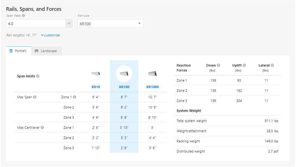
For roof top systems, the XR100 will automatically be set, this is the recommended series for residential roof applications, however the XR10 and XR1000 can also be selected. For most residential roof mount systems, the XR100 will provide ample support and structural integrity for your system without increasing the cost of racking components. A list of Roof Section Details will be outlined at the bottom of the page and you can move forward to your bill of materials list.
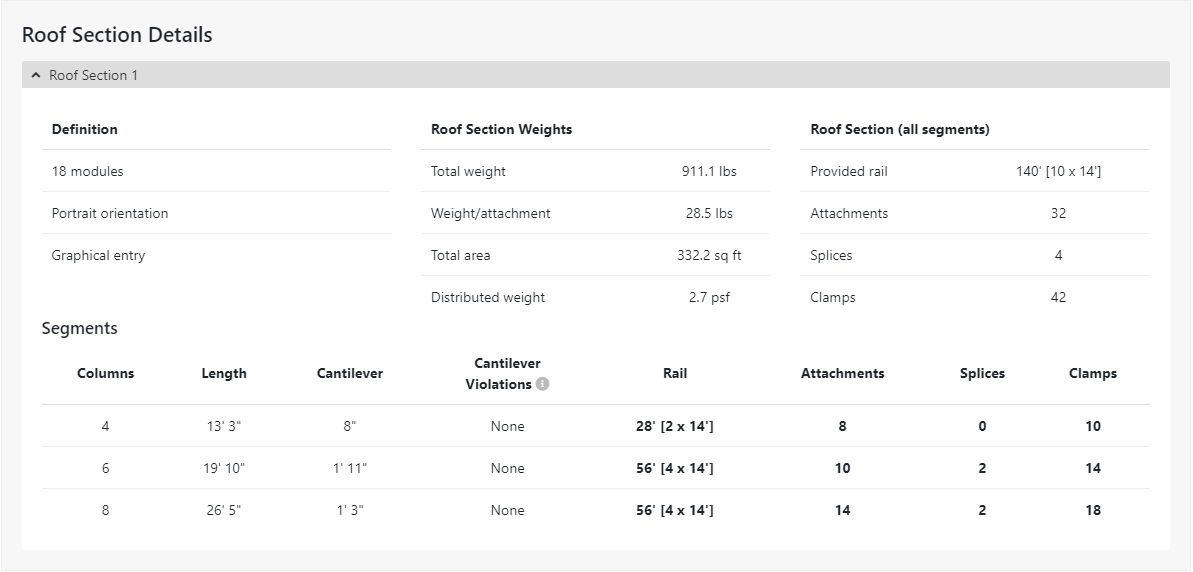
On the bill of materials list, you will see a complete list of quantities and part number of the necessary components for your racking system. Here you can add wire clips for wire management of the system, end caps for a finished look and debris protector for the rails, microinverter attachment hardware for microinverter and optimizer mounting and conduit mounts to run supports.
All components are recommended, though if you are using a string inverter without optimizers the micro attachment hardware will not be necessary. Likewise, conduit mounts will not be compatible with metal or tile roof installs.
See Here: IronRidge Pitched Roof Design Tool
b. Design an IronRidge Tilt Leg System
To create a Tilt leg system, select “Attached Flat” from the list of New Project options. You will complete the first few steps present in the flush mount design (address and project information). Under Roof Information, you will find your first changes. To start creating a Tilt Leg system and not a Flat Roof Attachment system, change the Roof attachment to none and save the roof information.
Next, you will determine the Angle and Spacing, first select the desired degree, keep in mind 25° to 30° tilts are the most desirable for the majority of locations. Be sure to account for your existing slope if one is present. You will then select your Inter-row spacing in inches, this is the amount of space between the panels to avoid shading, if no value is input the tool will calculate 0”.
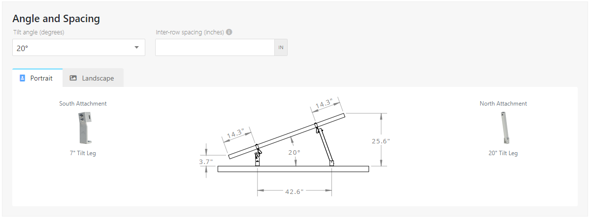
The next steps for completion are the same, select your span and rail type, an overview of the sub array details and onto the bill of materials where you can add your desired accessories.
See Here: IronRidge Attached Flat Roof Design Tool
c. Design an IronRidge Flat Roof Attachment System
To design a Flat Roof Attachment System, select “Attached Flat” form the list of design options and keep the roof attachment option set to Flat Roof Attachment. If you know your roofing material, indicate yes and enter the roof information (roof material, roof manufacturer, color and thickness). If you do not know the roofing material, select "no" and you can move onto the next steps.
It is important to note that you should confirm the roof material prior to purchase to ensure that you are getting the correct mounts and membranes for your solar energy project.
| Roof Material | Compatible Manufacturers | Colors | Thickness (mils) |
| TPO | Cralisle, Firestone, GAF, Johns Manville, Mule-Hide, Other | White, Black, Gray, Tan | 45, 60, 80 |
| KEE | Cralisle, Other | White, Black, Gray, Tan | 45, 60, 80 |
| PVC | GAF, Mule-Hide, Sika Sarnafil, Other | White, Black, Gray, Tan | 45, 60, 80 |
| Built-Up | Other | White, Black, Gray, Tan | 45, 60, 80 |
| Modified Bitumen | Other | White, Black, Gray, Tan | 45, 60, 80 |
| EPDM | Other | White, Black, Gray, Tan | 45, 60, 80 |
The above chart depicts the various options available in the design tool for easy sorting.

The design tool will indicate whether or not there is a waterproofing membrane that is compatible with your exact roof combination. If the tool indicates that there is not a current solution, contact their tech support to create a special order.
Here you will again set your desired tilt angle and inter-row spacing for the tilt leg attachments, then you will review and confirm the spans, rails and system information before moving onto the final bill of materials and selecting your accessories.
See Here: IronRidge Attached Flat Roof Design Tool
d. Design an IronRidge BX Chassis System
To design a ballast bay system using the BX Chassis, you will verify your address and input your project information. Here, you will a field labeled “ASCE Code” 7-10 is automatically filled and is not editable. Both the snow load and wind speed are marked to verify, after clicking you will be taken to ATC’s website to verify that the data is correct. Ballast systems can weigh a great deal and must adhere to strict structural and load standards, so be sure to verify that the information listed is correct.
Next, you will enter the Building Information by first inputting the building height, north-south and east-west measurements in feet. Ballast calculations require rectangular buildings and accurate dimensions. Non-rectangular buildings are encouraged to fill out the project details to the best of their ability and contact support directly for assistance.
Continuing on the Building information, you will list the roof slope (between 0° and 7°), the parapet height, and roofing material, manufacturer, color and thickness (just like the flat roof attachment). After inputting this data, you will be taken to the PX Parameters section to begin building out your array.
Many of the parameters for the system are predetermined, however it is important to look through the options to ensure you are designing the best array for your roof top. IronRidge requires designers to input the Spectral Acceleration and Seismic Design Category for their location. You will also set the inverter(s) that will be used with the system under power electronics.
If you are using a string inverter you will need to specify the number of inverter mounting bases you will need for the project (if any) and specify whether the inverter is a single or dual design. When using an optimizer and inverter system, you will input the mounting bases and specify if you need the MLPE microinverter and optimizer attachment hardware. This is recommended to make the installation of both microinverters and optimizers quick and easy within the system.
The tool will automatically generate a grid for your array, here you will manually fill in the number of panels you are using as well as the design by either clicking, holding and dragging the mouse across the area you want to fill in panels or including them individually. This is especially helpful for roof top systems that have obstacles that the array needs to be designed around.
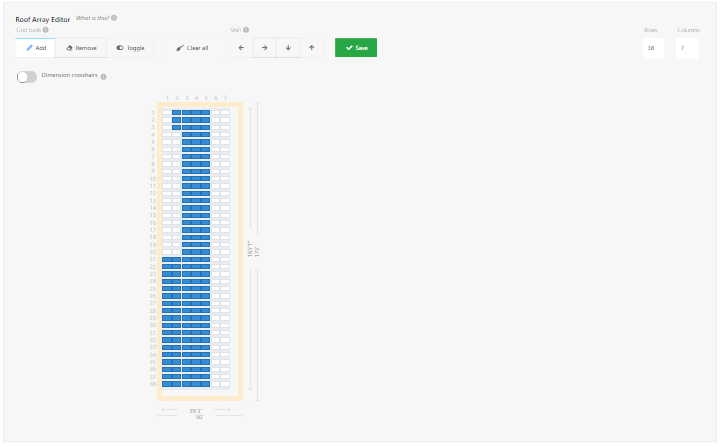
After saving, you can view your results on an interactive grid of the system. You can click on either the modules or chassis to view details such as the ballast required, chassis weight, number of blocks, block weight and total weight of that particular area. After confirming your information and design, you can move onto the bill of materials and add cable ties and/or edge clips with cable times for easy cable management.
See Here: IronRidge Ballasted Flat Design Tool
e. Design an IronRidge Ground Mount System
After inputting your site geo-location information and project information you will select your substructure and foundation. Here, you will select the desired tilt angle for your system, (25° or 30° is recommended for most locations), you will also choose between 2” pipe and 3” pipe, 3” is recommended due to the higher load the wider circumference can handle. Additional mounting piers are needed for 2” design systems, which ultimately balances out the outside cost of the schedule 40 pipe.
You will also set your soil class and hole diameter, the tool is set to 12”, with options of 16”, 20” and 24”. The hole diameter will determine how deep the foundation hole will need to be, the narrower the diameter the deeper the foundation will need to be. Typically, systems are designed with 16” or 20”, you can change the data and refer to your array to get an overview of the structure and hole depth of your system.
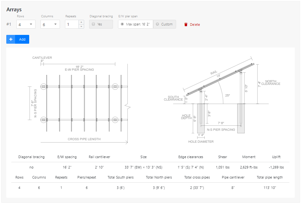
IronRidge Ground Mount Systems can be designed between 3 and 5 panels high, depending on the manufacturer and model number of the panel you are using. They are structurally sound for large systems, i.e. four panels high and 17 across without the need for additional bracing in many areas. However, if you live in an area with heavy snow loads or high wind speeds, additional bracing may be added in this step. After completing your design, you will move onto the bill of materials to add additional accessories and download your project documentation.
See Here: IronRidge Ground Mount Design Tool
As highlighted by the breadth of information and options highlighted above, IronRidge has a number of options suitable for a variety of applications in both residential and commercial solar energy projects. The racking is compatible with a number of roofing types and can be installed in a variety of configurations. Sites with flat or low sloped roofs have a number of options to choose from, and the ground mount equipment ensures high load capabilities at an excellent value cost.
The XR10 and XR100 rails are available in both black and silver, along with matching attachment hardware for a cohesive and polished look for any roof mount installation. The number of options for flat roofs makes it easier than ever before to design a highly efficient solar energy system at the ideal angle for your project. While their ground mount systems offer installers a wide array of options to design and install sturdy ground mount arrays.
The XR rails are built to withstand a wide array of site conditions from little to high snow loads and high wind speeds. Their equipment has been tested and certified in a number of states and are compatible with the majority of solar panels on the market. If there is not an immediate solution available for your solar racking system, you can work with IronRidge to create a custom system that is sure to fit your needs at an affordable price point.
IronRidge racking is one of Solaris’s top recommended racking solutions due to their versatility, high durability, structural integrity, ease of installation, and outstanding support. Their online design tools are easily accessible and workable for both professional installers and one-time do it yourself homeowners.
We strongly recommend considering using IronRidge racking and mounting solutions for your solar energy system. As always, if you need assistance creating a system, or would like us to design one for you, request a quote below.
Request an IronRidge Racking Quote


